

How to Reduce AOI False Calls: Root Causes & Fixes
Which AOI false calls you can tune away, which ones live below the threshold layer, and how to tell the difference before you buy another round of tuning hours.
July 28, 2026
See how AOI identifies visible open solder joints, where fixed color thresholds struggle, and how a pretrained 2D model handles common and special cases.
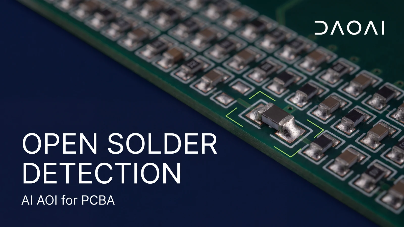
An open solder joint leaves a component lead or termination without its intended soldered connection to the pad. When that condition is visible, AOI can help find it before the assembly moves to the next stage.
The challenge is separating acceptable solder appearance from a defect. A useful inspection method needs to handle both, including the variations found across different boards and components. Here is how color rules approach that task and how DaoAI's pretrained 2D model handles open solder defects.
An open solder joint lacks the intended soldered connection between a component lead or termination and its pad. AOI examines visible evidence of that condition in the inspection image. During review, identify the affected termination and inspect the connection area against the assembly's acceptance criteria. Electrical continuity is checked through electrical testing.
Several solder defects can occur around the same termination. Keeping the classifications clear helps engineers prepare consistent training samples and review inspection results.
| Condition | What it describes | Review focus |
|---|---|---|
| Open solder joint | A missing soldered connection | The intended connection between the termination and pad |
| Insufficient solder | Too little solder for the applicable joint requirements | Solder coverage and the required joint formation |
| Cold solder joint | An inadequately formed solder joint | Joint formation and supporting inspection evidence |
| Lifted lead | A lead raised from its intended position | Lead position and its connection to the pad |
| Acceptable sample | Open solder sample |
|---|---|
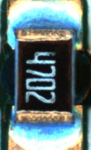 |
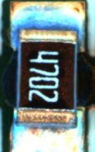 |
A color based rule measures selected colors inside a region of interest, or ROI. It can count matching pixels or calculate their share of the region, then compare that measurement with an acceptance limit. The result depends on the captured image, the chosen region and the rule settings. Lighting and camera configuration therefore need to remain consistent.
A simple color area check has four steps:
Fixed color thresholds become difficult to set when acceptable and defective joints produce similar measurements. Widening the range can reduce false calls while also admitting defects. Tightening it can catch more defects while rejecting acceptable joints. The practical question is whether the selected measurement separates the two groups across the boards and conditions you need to inspect.
Two situations are worth checking:
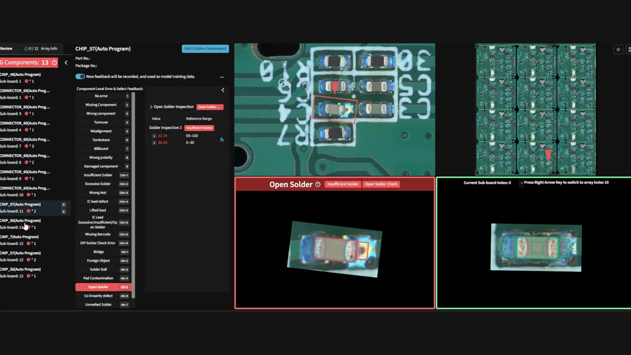
DaoAI's pretrained 2D model covers most common open solder cases and can be used directly. For special cases, add the relevant samples in the software and train the model to correct how those cases are classified.
See the in software model training workflow.
Which AOI false calls you can tune away, which ones live below the threshold layer, and how to tell the difference before you buy another round of tuning hours.
July 28, 2026
No CAD files, no component library — how golden-board AI programming actually works step by step, and how it compares to the traditional 3–5 hour AOI workflow.
July 21, 2026
Vendor ROI calculators decide the assumptions for you. Here is the whole model: eight cost lines, the formulas for false-call and escape savings, and two worked scenarios including one that does not pay.
August 25, 2026
AI inspection insights, product news, and industry analysis. Once a month, no noise.